
Dual output Flyback converter SMPS design using Tiny Switch 4 not Working.
Hi,
I have tried to build an SMPS with 5V, 0.6 A and 5V, 0.1 A output to operate at the universal voltage from the design file generated by PI Expert online. The device will power up and function to give 5 V at the output1and 8v at output 2 if the load connected are 100ohm and 1.5Kohm respectively. Now if I connect 100-ohm load at both the output, it powers up and shuts down.
I think the load draws too much current and for that reason the tiny switch-4 shutdowns.
Can someone help me with this problem?
I have attached my schematic.
Thanks,
Rushab
Files
| Attachment | Size |
|---|---|
| SMPS_Schematic.pdf | 148.54 KB |
Comments
Hi,
I have attached the PI Expert document along with its transformer documentation.
I have used different core material just for availability purpose, I have attached the details.
| Attachment | Size |
|---|---|
| TinySwitch-4_PIDesign1.uds | 2.02 MB |
| Transformer_Details.pdf | 93.83 KB |
Hi,
Can you please attach the .xls file generated from PI Expert online?
The restrictions on my computer do not allow me to access .uds file
Best Regards,
PI-Kryten
Hi,
I cannot upload .xls file here I have attached the pdf version of it.
| Attachment | Size |
|---|---|
| PI_Expert_Online_BOM.pdf | 104.9 KB |
Hi,
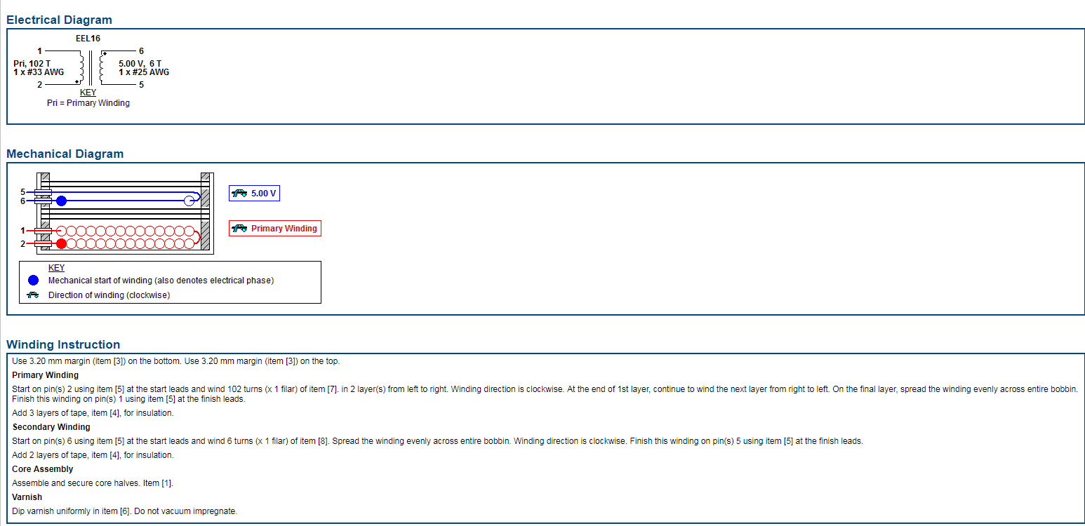
Thank you for sharing the BOM. Can you kindly share the design results and transformer design details generated by PI Expert such as the pictures attached to this thread?
Best Regards,
PI-Kryten
| Attachment | Size |
|---|---|
| Transformer_details.PNG | 43.28 KB |
| Design.PNG | 53.31 KB |
Hi,
I have attached the design results and transformer details below.
| Attachment | Size |
|---|---|
| Transformer_DetailsPI.pdf | 116.49 KB |
| PI_Expert_Online_DEsign_results.pdf | 124.78 KB |
Hi,
The transformer design looks ok. It is not very clear as to what exactly is going wrong.
I would suggest a stage by stage check. Kindly check if you are able to obtain the expected waveforms starting from the Input section, input to the transformer, the output of the transformer (will confirm the polarity of windings) and then the output.
Hope this helps
Regards,
PI-Kryten
Hi,
Thank you for choosing Power Integrations for your solution.
Can you kindly attach the PI Expert document along with its transformer documentation?This will help us determine if it has been designed to handle that much power.
Best Regards,
PI-Kryten